
Image: Hertz radio wave experiments - crossed polarization
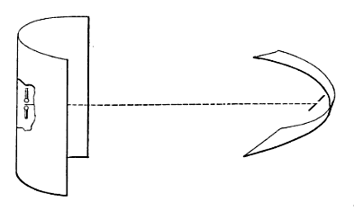
Description: Diagram of experiment performed by Heinrich Hertz in 1888 demonstrating polarization of radio waves. At left is Hertz's spark-gap transmitter consisting of a dipole antenna of two brass bars with a spark gap between them, powered by high voltage from a Ruhmkorff coil (not shown) attached to the dipole. High voltage from the coil causes sparks to jump between the halves of the dipole, creating high frequency oscillating currents in the dipole which radiate a pulse of radio waves. At right is Hertz's receiver, consisting of a similar dipole and parabolic reflector attached to a micrometer spark gap. The transmitter dipole was 26 cm long and generated radio waves in the UHF band at about 450 MHz. When the two dipoles are perpendicular at a 90° angle, as shown here, the receiver doesn't produce any sparks. As the receiver dipole is rotated closer to parallel with the transmitter, it begins to produce sparks, and when it is parallel with the transmitter it produces maximum length sparks. This indicates that the radio waves emitted by the transmitter are linearly polarized, with the electric field parallel to the dipole element, and the receiver dipole responds to the component of the electric field parallel to its dipole. This is similar to the way linearly polarized light acts.
Title: Hertz radio wave experiments - crossed polarization
Credit: Retrieved December 17, 2015 from George Washington Pierce (1910) Principles of Wireless Telegraphy, McGraw-Hill Book Co., New York, p. 53, fig. 31 on Google Books
Author: George Washington Pierce
Usage Terms: Public domain
License: Public domain
Attribution Required?: No
Image usage
The following page links to this image:
