
Image: Hertz radio wave experiments - refraction
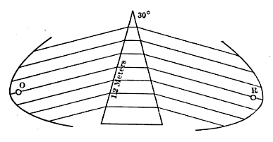
Description: Diagram of experiment performed by Heinrich Hertz in 1888 demonstrating refraction of radio waves. At left is Hertz's spark-gap transmitter consisting of a dipole antenna of two brass bars with a spark gap between them, powered by high voltage from a Ruhmkorff coil (not shown) attached to the dipole. High voltage from the coil causes sparks to jump between the halves of the dipole, creating high frequency oscillating currents in the dipole which radiate a pulse of radio waves. At right is Hertz's receiver, consisting of a similar dipole and parabolic reflector attached to a micrometer spark gap. The transmitter and receiver are seen end on; the reflectors were actually 2 m long. The transmitter generated 66 cm radio waves in the UHF band at about 450 MHz. Between the transmitter and receiver Hertz placed a prism of pitch 1.5 m high with an angle of 30°. With the apparatus as shown Hertz found the prism bent the radio waves through an angle of 22°, similarly to the way a glass prism would bend a ray of light. From this angle Hertz calculated that the index of refraction of the pitch for radio waves was 1.69.
Title: Hertz radio wave experiments - refraction
Credit: Retrieved December 17, 2015 from George Washington Pierce (1910) Principles of Wireless Telegraphy, McGraw-Hill Book Co., New York, p. 55, fig. 34 on Google Books
Author: George Washington Pierce
Usage Terms: Public domain
License: Public domain
Attribution Required?: No
Image usage
The following page links to this image:
