
Image: Hertz transmitter and receiver - English

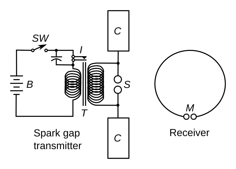
Description: Experimental circuit used by Heinrich Hertz in 1887 to discover radio waves. It is a spark gap radio transmitter (left) consisting of a dipole antenna made of two horizontal wires with metal plates on the ends (C) to add capacitance, with a spark gap (S) between them, attached to an induction coil (T) powered by a battery (B). Pulses of high voltage applied to the antenna by the induction coil cause sparks across the spark gap, which excite standing waves of current in the antenna, causing it to radiate electromagnetic waves (radio waves). The waves were detected by a crude receiver consisting of a resonant loop antenna (right) made of a circle of wire, with a micrometer spark gap (M) between its ends. The device actually produced single short pulses of radio waves; when Hertz pushed the switch (SW) in the primary circuit of the coil, a single spark would jump across the transmitting antenna, creating a radio wave pulse that would induce a single tiny spark in the receiver loop. The frequency of the waves was determined by the length of the antenna which acted as a half-wave dipole; the short antennas Hertz used produced high frequency waves in the UHF band, about the frequency of modern television transmitters.
Title: Hertz transmitter and receiver - English
Credit: From File:Hertz Transmitter Receiver.svg. Alterations to image: Changed labels to English, labeled individual parts, increased thickness of lines, cropped empty space
Author: Original version: DMGualtieri This version: Chetvorno
Usage Terms: Creative Commons Attribution-Share Alike 3.0
License: CC BY-SA 3.0
License Link: https://creativecommons.org/licenses/by-sa/3.0
Attribution Required?: Yes
Image usage
The following page links to this image:
