
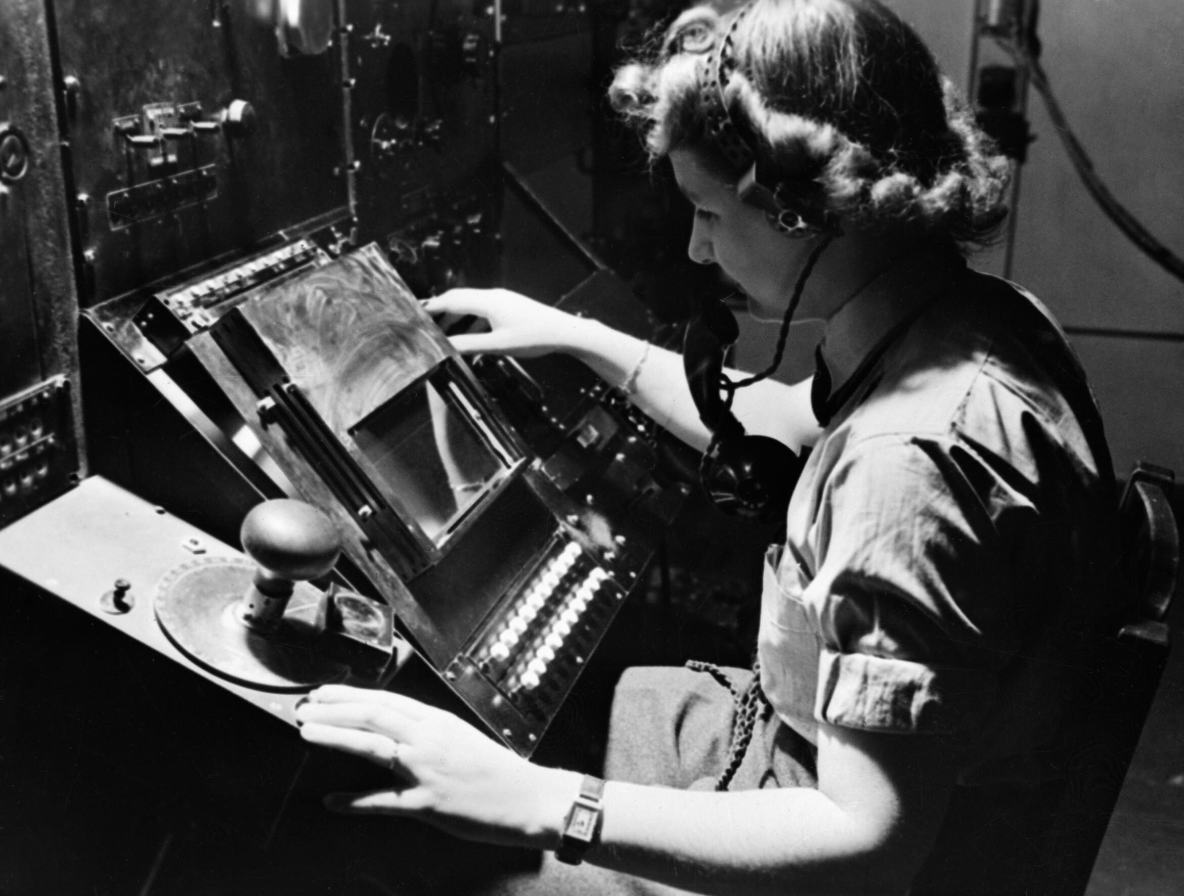
Image: WAAF radar operator Denise Miley plotting aircraft on a cathode ray tube in the Receiver Room at Bawdsey 'Chain Home' station, May 1945. CH15332
Description: Original description from RAF Museum page: "Chain Home: WAAF radar operator Denise Miley plotting aircraft on the CRT (cathode ray tube) of an RF7 Receiver in the Receiver Room at Bawdsey CH. Her right hand has selected the direction or height finding and her left hand is ready to register the goniometer setting to the calculator." RAF Bawdsey was originally an experimental system set up at Bawdsey Manor, home of Robert Watson-Watt's radar development team. When the team was moved away from Bawdsey, the radar station became a part of the operational Chain Home (CH) network. The main display is a large CRT, partially masked off by a metal box so only the lower half of the CRT remains visible. In earlier versions a scale running across the top of the opening allowed the range to the target to be measured. In this later version, a knob is used to move a cursor line across the screen to lie over a selected return. The cursor is driven by the same timing electronics as the rest of the radar, ensuring it is properly calibrated at all times. The large knob on the left of the image is the goniometer control. Unlike later systems, CH used separate transmitters and receivers. The transmitter broadcast a semi-directional signal in front of the station, known as the "line of shoot", filing space with the signal. The receiver was a radio direction finder that searched that space for echoes. The goniometer knob changed the directional sensitivity of the receivers, allowing the angle to the target to be determined. This was a trial-and-error process of hunting for the maximum (or minimum) return in a noisy signal. Like most RDF systems, the antennas were equally sensitive in two directions; the small push-button to the upper left of the knob, the "sense button", mutes down one of these directions to determine which one is correct. This button is not visible in the cropped but higher quality version of the image seen here, it can be selected below. A series of switches near Miley's right hand are used to select among several antennas on the receiver masts. Selecting a pair of these allows the goniometer to determine vertical angles instead of horizontal azimuth. With some calculation effort, this could be used to determine altitude. Additional crewmembers known as "plotters", normally located behind the operator, were sent a stream of angle and range information and had to calculate the map location of the targets being measured. These were then reported up the Dowding system's telephone network to Fighter Command headquarters in London. Due to the noise caused by the different plotters calling out calculations to each other, the radar operator was connected to the main plotter via the intercom Miley wears around her neck. This version, from later in the war, has been equipped with sensors to automate the plotting of the aircraft. One of these sensors can be seen attached to the goniometer control, the box-like object to the right of Miley's left hand. After measuring an angle with the goniometer and setting the cursor to measure the range of the selected "blip", the button under Miley's left hand was pressed to send these settings to a mechanical computer known as the "fruit machine". It carried out all of these calculations internally and then directly output the map location and altitude of the targets. This greatly reduced workload and allowed the stations to have smaller crews. The metal box covering the CRT is also a later addition, a simple anti-jamming system. The Germans could jam the CH stations by broadcasting false echoes when they received a pulse from the CH station. These false signals were only partially synchronized, deliberately, so they jumped around the display and cluttered it up. The CRT was originally supplied with a fast-acting phosphor of a light blue color, but was later modified by placing a second layer of slower-acting, less-sensitive yellow phosphor on top. Signals that stayed in the same location long enough would cause the yellow layer to begin glowing in that location. When encountering jamming, the operator would pull the small metal tabs on the left side of the metal cover to move a yellow-coloured gel in front of the tube, filtering out the now noisy blue layer and leaving only the stable (but slower reacting) yellow signals visible. The marks on the metal cover suggest it has been used as an impromptu chalkboard. In this example, the radar receiver system and display are co-located. In later setups, the display was removed from the receiver and placed beside the plotting boards. This provided a much more compact layout and allowed the plotters to see the display directly. Although it cannot be seen in this photo, the shaft from the goniometer runs out the bottom of the display cabinet and into the receiver chassis, and can be seen to be at a slightly different angle than the display itself. The later systems combined this into a single cabinet.
Title: WAAF radar operator Denise Miley plotting aircraft on a cathode ray tube in the Receiver Room at Bawdsey 'Chain Home' station, May 1945. CH15332
Credit: http://media.iwm.org.uk/iwm/mediaLib//39/media-39665/large.jpg This photograph CH 15332 comes from the collections of the Imperial War Museums.
Author: Goodchild (Flt Lt), Royal Air Force official photographer
Permission: This image was created and released by the Imperial War Museum on the IWM Non Commercial Licence. Photographs taken, or artworks created, by a member of the forces during their active service duties are covered by Crown Copyright provisions. Faithful reproductions may be reused under that licence, which is considered expired 50 years after their creation.
Usage Terms: Public domain
License: Public domain
Attribution Required?: No
Image usage
The following page links to this image:
