
Lock (water transport) facts for kids


A lock is a device used for raising and lowering boats, ships and other watercraft between stretches of water of different levels on river and canal waterways. The distinguishing feature of a lock is a fixed chamber in which the water level can be varied; whereas in a caisson lock, a boat lift, or on a canal inclined plane, it is the chamber itself (usually then called a caisson) that rises and falls.
Locks are used to make a river more easily navigable, or to allow a canal to cross land that is not level. Later canals used more and larger locks to allow a more direct route to be taken.
Since 2016, the largest lock worldwide is the Kieldrecht Lock in the Port of Antwerp, Belgium.
Contents
Pound lock

A pound lock is a type of lock that is used almost exclusively nowadays on canals and rivers. A pound lock has a chamber with gates at both ends that control the level of water in the pound. In contrast, an earlier design with a single gate was known as a flash lock.
Pound locks were first used in medieval China during the Song Dynasty (960–1279 AD), having been pioneered by the Song politician and naval engineer Qiao Weiyue in 984. They replaced earlier double slipways that had caused trouble and are mentioned by the Chinese polymath Shen Kuo (1031–1095) in his book Dream Pool Essays (published in 1088), and fully described in the Chinese historical text Song Shi (compiled in 1345):
The distance between the two locks was rather more than 50 paces, and the whole space was covered with a great roof like a shed. The gates were 'hanging gates'; when they were closed the water accumulated like a tide until the required level was reached, and then when the time came it was allowed to flow out.
The water level could differ by 4 feet (1.2 m) or 5 feet (1.5 m) at each lock and in the Grand Canal the level was raised in this way by 138 feet (42 m).
In medieval Europe a sort of pound lock was built in 1373 at Vreeswijk, Netherlands. This pound lock serviced many ships at once in a large basin. Yet the first true pound lock was built in 1396 at Damme near Bruges, Belgium. The Italian Bertola da Novate (c. 1410–1475) constructed 18 pound locks on the Naviglio di Bereguardo (part of the Milan canal system sponsored by Francesco Sforza) between 1452 and 1458.

When a stretch of river is made navigable, a lock is sometimes required to bypass an obstruction such as a rapid, dam, or mill weir – because of the change in river level across the obstacle.
In large scale river navigation improvements, weirs and locks are used together. A weir will increase the depth of a shallow stretch, and the required lock will either be built in a gap in the weir, or at the downstream end of an artificial cut which bypasses the weir and perhaps a shallow stretch of river below it. A river improved by these means is often called a Waterway or River Navigation (see example Calder and Hebble Navigation).
Sometimes a river is made entirely non-tidal by constructing a sea lock directly into the estuary.
In more advanced river navigations, more locks are required.
- Where a longer cut bypasses a circuitous stretch of river, the upstream end of the cut will often be protected by a flood lock.
- The longer the cut, the greater the difference in river level between start and end of the cut, so that a very long cut will need additional locks along its length. At this point, the cut is, in effect, a canal.
Use in canals

Early completely artificial canals, across fairly flat countryside, would get round a small hill or depression by simply detouring (contouring) around it. As engineers became more ambitious in the types of country they felt they could overcome, locks became essential to effect the necessary changes in water level without detours that would be completely uneconomic both in building costs and journey time. Later still, as construction techniques improved, engineers became more willing to cut directly through and across obstacles by constructing long tunnels, cuttings, aqueducts or embankments, or to construct even more technical devices such as inclined planes or boat lifts. However, locks continued to be built to supplement these solutions, and are an essential part of even the most modern navigable waterways.
Basic construction and operation

| For a boat going upstream: |  |
For a boat going downstream: | ||
|---|---|---|---|---|
| 1–2. | The boat enters the lock. | 8–9. | The boat enters the lock. | |
| 3. | The lower gates are closed. | 10. | The upper gates are closed. | |
| 4–5. | The lock is filled with water from upstream. | 11–12. | The lock is emptied by draining its water downstream. | |
| 6. | The upper gates are opened. | 13. | The lower gates are opened. | |
| 7. | The boat exits the lock. | 14. | The boat exits the lock. | |
All pound locks have three elements:
- A watertight chamber connecting the upper and lower canals, and large enough to enclose one or more boats. The position of the chamber is fixed, but its water level can vary.
- A gate (often a pair of "pointing" half-gates) at each end of the chamber. A gate is opened to allow a boat to enter or leave the chamber; when closed, the gate is watertight.
- A set of lock gear to empty or fill the chamber as required. This is usually a simple valve (traditionally, a flat panel (paddle) lifted by manually winding a rack and pinion mechanism) which allows water to drain into or out of the chamber; larger locks may use pumps.
The principle of operating a lock is simple. For instance, if a boat travelling downstream finds the lock already full of water:
- The entrance gates are opened and the boat moves in.
- The entrance gates are closed.
- A valve is opened, this lowers the boat by draining water from the chamber.
- The exit gates are opened and the boat moves out.
If the lock were empty, the boat would have had to wait 5 to 10 minutes while the lock was filled. For a boat travelling upstream, the process is reversed; the boat enters the empty lock, and then the chamber is filled by opening a valve that allows water to enter the chamber from the upper level. The whole operation will usually take between 10 and 20 minutes, depending on the size of the lock and whether the water in the lock was originally set at the boat's level.
Boaters approaching a lock are usually pleased to meet another boat coming towards them, because this boat will have just exited the lock on their level and therefore set the lock in their favour – saving about 5 to 10 minutes. However, this is not true for staircase locks, where it is quicker for boats to go through in convoy.

Details and terminology

For simplicity, this section describes a basic type of lock, with a pair of gates at each end of the chamber and simple rack and pinion paddles raised manually by means of a detachable windlass operated by lock-keepers or the boat's shore crew. This type can be found all over the world, but the terminology here is that used on the British canals. A subsequent section explains common variations.
Rise
The rise is the change in water-level in the lock. The two deepest locks on the English canal system are Bath deep lock on the Kennet and Avon Canal and Tuel Lane Lock on the Rochdale Canal, which both have a rise of nearly 20 feet (6.1 m). Both locks are amalgamations of two separate locks, which were combined when the canals were restored to accommodate changes in road crossings. The deepest "as-built" locks in England are considered to be Etruria Top Lock on the Trent and Mersey Canal and Somerton Deep Lock on the Oxford Canal: both have a rise of about 14 ft (4.3 m). Again, sources vary as to which is the deepest, and in any case Etruria has been deepened over the years to accommodate subsidence. A more typical rise (in England) would be 7–12 feet (2.1–3.7 metres) (though even shallower ones can be encountered). By comparison, the Carrapatelo and Valeira locks on the Douro river in Portugal, which are 279 feet (85 m) long and 39 feet (12 m) wide, have maximum lifts of 115 feet (35 m) and 108 feet (33 m) respectively. The two Ardnacrusha locks near Limerick on the Shannon navigation in Ireland have a rise of 100 feet (30 m). The upper chamber rises 60 feet (18 m) and is connected to the lower chamber by a tunnel, which when descending does not become visible until the chamber is nearly empty.
Pound
A pound is the level stretch of water between two locks (also known as a reach). On American canals, a pound is called a level.
Chamber
The chamber is the main feature of a lock. It is a watertight (masonry, brick, steel or concrete) enclosure which can be sealed off from the pounds at both ends by means of gates. The chamber may be the same size (plus a little manoeuvring room) as the largest vessel for which the waterway was designed; sometimes larger, to allow more than one such vessel at a time to use the lock. The chamber is said to be "full" when the water level is the same as in the upper pound; and "empty" when the level is the same as in the lower pound. (If the lock has no water in it at all, perhaps for maintenance work, it might also be said to be empty, but it is more usually described as "drained" or "de-watered".)
Cill
The cill, also spelled sill, is a narrow horizontal ledge protruding a short way into the chamber from below the upper gates. Allowing the rear of the boat to "hang" on the cill is the main danger one is warned to guard against when descending a lock, and the position of the forward edge of the cill is usually marked on the lock side by a white line. The edge of the cill is usually curved, protruding less in the center than at the edges. In some locks, there is a piece of oak about 9 in (23 cm) thick which protects the solid part of the lock cill. On the Oxford Canal it is called a Babbie; on the Grand Union Canal it is referred to as the cill Bumper. Some canal operation authorities, primarily in the United States and Canada, call the ledge a miter sill (mitre sill in Canada).
Photo gallery
-
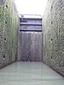
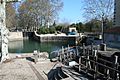
The cill exposed in the deep Pont de Flandre lock on the Canal Saint-Denis, Paris
-
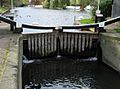
Top gate of a lock, showing the balance beams and paddle winding gear
-
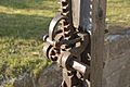
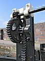
200-year-old paddle gear on the Wiener Neustädter Kanal, Austria
-
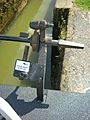
Water conservation gear on the Birmingham Canal Navigations
-
Lock gate controls on a canal


Gates
Gates are the watertight doors which seal off the chamber from the upper and lower pounds. Each end of the chamber is equipped with a gate, or pair of half-gates, made of oak or elm (or now sometimes steel). The most common arrangement, usually called miter gates, was invented by Leonardo da Vinci, sometime around the late 15th century. When closed, a pair meet at an angle like a chevron pointing upstream and only a very small difference in water-level is necessary to squeeze the closed gates securely together. This reduces any leaks from between them and prevents their being opened until water levels have equalised. If the chamber is not full, the top gate is secure; and if the chamber is not completely empty, the bottom gate is secure (in normal operation, therefore, the chamber cannot be open at both ends). A lower gate is taller than an upper gate, because the upper gate only has to be tall enough to close off the upper pound, while the lower gate has to be able to seal off a full chamber. The upper gate is as tall as the canal is deep, plus a little more for the balance beam, winding mechanism, etc.; the lower gate's height equals the upper gate plus the lock's rise.
Balance beam
A balance beam is the long arm projecting from the landward side of the gate over the towpath. As well as providing leverage to open and close the heavy gate, the beam also balances the (non-floating) weight of the gate in its socket, and so allows the gate to swing more freely.
Paddle
A paddle – sometimes known as a slacker, clough, or (in American English) wicket – is the simple valve by which the lock chamber is filled or emptied. The paddle itself is a sliding wooden (or nowadays plastic) panel which when "lifted" (slid up) out of the way allows water to either enter the chamber from the upper pound or flow out to the lower pound. A gate paddle simply covers a hole in the lower part of a gate; a more sophisticated ground paddle blocks an underground culvert. There can be up to 8 paddles (two gate paddles and two ground paddles at both upper and lower ends of the chamber) but there will often be fewer. For a long period since the 1970s it was British Waterways policy not to provide gate paddles in replacement top gates if two ground paddles existed. The reason for this was given as safety, since it is possible for an ascending boat to be swamped by the water from a carelessly lifted gate paddle. However, without the gate paddles the locks are slower to operate and this has been blamed in some places for causing congestion. Since the late 1990s the preferred method has been to retain or re-install the gate paddles and fit 'baffles' across them to minimise the risk of inundation.
On the old Erie Canal, there was a danger of injury when operating the paddles: water, on reaching a certain position, would push the paddles with a force which could tear the windlass (or handle) out of one's hands, or if one was standing in the wrong place, could knock one into the canal, leading to injuries and drownings.
Winding gear or paddle gear
Winding gear is the mechanism which allows paddles to be lifted (opened) or lowered (closed). Typically, a square-section stub emerges from the housing of the winding gear. This is the axle of a sprocket ("pinion") which engages with a toothed bar ("rack") attached by rodding to the top of the paddle. A lock-keeper or member of the boat's shore crew engages the square socket of their windlass (see below) onto the end of the axle and turns the windlass perhaps a dozen times. This rotates the pinion and lifts the paddle. A pawl engages with the rack to prevent the paddle from dropping inadvertently while being raised, and to keep it raised when the windlass is removed, so that the operator can attend to other paddles. Nowadays it is considered discourteous and wasteful of water to leave a paddle open after a boat has left the lock, but in commercial days it was normal practice. To lower a paddle the pawl must be disengaged and the paddle wound down with the windlass. Dropping paddles by knocking the pawl off can cause damage to the mechanism; the paddle gear is typically made of cast iron and can shatter or crack when dropped from a height. In areas where water-wastage due to vandalism is a problem, (for example the Birmingham Canal Navigations), paddle mechanisms are commonly fitted with vandal-proof locks (nowadays rebranded "water conservation devices") which require the boater to employ a key before the paddle can be lifted. The keys are officially known as "water conservation keys", but boaters usually refer to them as T-keys, from their shape; handcuff keys because the original locks, fitted on the Leeds and Liverpool Canal, resembled handcuffs; Leeds and Liverpool Keys after that canal; or simply Anti-Vandal Keys.
Hydraulic paddle gear
During the 1980s, British Waterways began to introduce a hydraulic system for operating paddles, especially those on bottom gates, which are the heaviest to operate. A metal cylinder about a foot in diameter was mounted on the balance beam and contained a small oil-operated hydraulic pump. A spindle protruded from the front face and was operated by a windlass in the usual way, the energy being transferred to the actual paddle by small bore pipes. The system was widely installed and on some canals it became very common. There turned out to be two serious drawbacks. It was much more expensive to install and maintain than traditional gear and went wrong more frequently, especially once vandals learned to cut the pipes. Even worse, it had a safety defect, in that the paddle once in the raised position could not be dropped in an emergency, but had to be wound down, taking a good deal longer. These factors led to the abandonment of the policy in the late 1990s, but examples of it survive all over the system, as it is usually not removed until the gates need replacing, which happens about every twenty years.
Windlass ("lock key")

A windlass (also variously 'lock handle', 'iron' or simply 'key') is a detachable crank used for opening lock paddles (the word does not refer to the winding mechanism itself).
The simplest windlass is made from an iron rod of circular section, about half an inch in diameter and two feet long, bent to make an L-shape with legs of slightly different length. The shorter leg is called the handle, and the longer leg is called the arm. Welded to the end of the arm is a square, sometimes tapered, socket of the correct size to fit onto the spindle protruding from lock winding gear.
- Socket: Traditionally, windlasses had a single socket, designed for a particular canal. When undertaking a journey through several canals with different lock-gear spindle sizes it was necessary to carry several different windlasses. A modern windlass usually has two sockets for use on different canals: the smaller is for the British Waterways standard spindle, fitted in the early 1990s almost everywhere, the larger for the gear on the Grand Union Canal north of Napton Junction, which they were unable/unwilling to convert.
- Handle: The handle is long enough for a two-handed grip and is far enough from the socket to give enough leverage to wind the paddle up or down. There may be a freely rotating sleeve around the handle to protect the hands from the friction of rough iron against skin.
- Arm: A "long throw" windlass has a longer arm so that the handle is further from the socket to give a greater leverage on stiffer paddles. If the throw is too long then the user, winding a gate paddle, risks barking their knuckles against the balance beam when the handle is at the lowest point of its arc. A sophisticated modern windlass may have an adjustable-length arm.
- Materials : Early windlasses were individually hand forged from a single piece of wrought iron by a blacksmith. More modern techniques include casting of iron or bronze, drop forging and (the most common technique) welding. Some boatmen had their windlasses 'silvered' (or chrome plated) for increased comfort and to prevent rusting. Windlasses are now only rarely plated, but a popular modern choice of metal is aluminium, whose smooth and rustproof surface has the same advantages of longevity and blister-reduction, and is also very light. One type of these, the Dunton Double, has only a single eye, but by clever tapering it will operate either size of spindle.
On the Chesapeake and Ohio Canal, the lockkeepers were required to remove the windlasses from all lock paddles at night, to prevent unauthorized use.
"Turning" a lock
"Turning" a lock can simply mean emptying a full lock, or filling an empty one ("We entered the lock, and it only took us five minutes to turn it"). It is used more often to refer to a lock being filled or emptied for the benefit of someone else ("The lock was turned for us by a boat coming the other way") and sometimes the opposite ("The lock was set for us, but the crew of the boat coming the other way turned it before we got there").
Swell or Swelling
A swell was caused by opening suddenly the paddle valves in the lock gates, or when emptying a lock. To help boats leave (downstream) a lock, the locksman would sometimes open the paddles to create a swell, which would help "flush" the boat out of the lock. In one case, a boatsman asked for a back swell, that is, open and shut the paddles a few times to create some waves, to help him get off the bank where he was stuck. If boats ran aground (from being overloaded) they sometimes asked passing crews to tell the upstream lock to give them an extra heavy swell, which consisted of opening all the paddles on the lock gate, creating a surge that affected the whole pound below.
On the Erie Canal, some loaded boats needed a swell to get out of the lock, particularly lumber boats, being top heavy, would list to one side and get stuck in the lock, and needed a swell to get them out. Some lockkeepers would give a swell to anyone to help them on the way, but some would ask for money for the swell.
The Erie Canal management did not like swelling for two reasons. First, it used too much water lowering the water on the pound above sometimes causing boats to run aground. In addition, it raised the water level on the pound below causing some boats to strike bridges or get stuck.
"Lock mooring"
"Lock mooring" was a commonly used method of navigating into a lock by a barge travelling upstream. The barge would be directed to the slack water to one side of the lock gates and as the volume of water decreased as the lock emptied the barge or boat is effectively sucked out of the slack water into the path of the lock gates. The effort required to navigate the barge or boat into the mouth of the lock was therefore substantially reduced.
Snubbing posts

On horse-drawn and mule-drawn canals, snubbing posts were used to slow or stop a boat in the lock. A 200-ton boat moving at a few miles an hour could destroy the lock gate. To prevent this, a rope was wound around the snubbing post as the boat entered the lock. Pulling on the rope slowed the boat, due to the friction of the rope against the post. A rope 2½ inches (6.3 cm) in diameter and about 60 feet (18 meters) long was typically used on the Erie Canal to snub a boat in a lock.
One incident, which took place in June 1873 on the Chesapeake and Ohio Canal, involved the boat the Henry C. Flagg and its drunk captain. That boat was already leaking; the crew, having partially pumped the water out, entered Lock 74, moving in front of another boat. Because they failed to snub the boat, it crashed into and knocked out the downstream gates. The outrush of water from the lock caused the upstream gates to slam shut, breaking them also, and sending a cascade of water over the boat, sinking it. This suspended navigation on the canal for 48 hours until the lock gates could be replaced and the boat removed from the lock.
Images for kids
-
Iroquois Lock on the Saint Lawrence Seaway
-
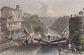
Doubled locks. Left lock has boat in it, right lock (center of drawing) is empty. This is on the Erie Canal at Lockport.
-
Agde Round Lock
-
Dalmuir drop lock
-
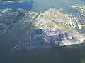
Berendrecht Lock (right) and Zandvliet Lock (left), located at the entrance to the Port of Antwerp (top) from the Scheldt (foreground)
-
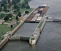
Barges at a lock on the Mississippi River
-
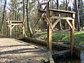
Model of early river pound lock, constructed in Lankheet water park, Netherlands
-
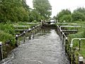
The turf-sided Monkey Marsh Lock on the Kennet & Avon Canal at Thatcham
-

Entrance to Minden shaft lock
.jpg)


See also
 In Spanish: Esclusa para niños
